

Drone Industry has been booming in India at a rate of over 40% a year. The B2B market for industrial and functional drones is huge and still growing and the market for recreational drones is also picking up. The number of indigenous drone manufacturing start-ups is also on the rise and so is the demand for custom manufactured drone parts. The way a drone is manufactured is contingent on that drone’s intended purpose. For example, recreational drones are mostly built out of plastic with injection molding. Hi-end and Racing Drones usually have their propellers and frame made out of Carbon fiber with resin transfer molding. Heavy-duty drones have a lot of Diecast or machined metal parts. Sometimes, premium drones are manufactured with metals because of its perceived quality and robustness. But whatever the application is, machining processes are indispensable. Whether be it manufacturing dies for Injection molding, Resin transfer molding, or Die casting, or be it using machined parts directly, machining is omnipresent. Despite the recent advances in plastics, polymers, and composites, metals confer certain unique advantages that make them irreplaceable.
MACHINING COMPONENTS
Machining is the process of cutting material off the blank in a systematic way to our required dimensions. Like any manufacturing process, one cannot manufacture any design, at least not easily. A seemingly trivial detail in the design can even double or triple your machining costs. Drones, by definition, - For civilian purposes – will not be any larger than 1 meter and much of its parts are invariably going to be very small (unlike automobile or machinery). Machining small parts often entail a great deal of complexity, and they are going to be expensive (when measured in the cost per unit material removed). But there are certain DFM tricks one can use to mitigate these problems. When it comes to machining, it always is simple. “Time is Money” as the costs are calculated based on the number of hours the machine and the operator are working to deliver your component. Understanding the complications can help us understand the solutions better.
MACHINED DRONE COMPONENTS
As mentioned earlier, in machining, time is money. And Machining time is usually split into setting time and machining time. The setting time will increase for tiny intricate components as they require special jigs. Machining time will also increase as there will be no room for rough machining; usually, machining, say an Automotive component, goes in two phases - a rough cut and a precision cut. The difference between them is the tool feed rate. When reducing the component size, there will not be enough material for the rough-cut level feed rate. So, the entire process is usually done in precision-cut level feed rate. As a consequence, after a certain threshold, the ratio of the time to the material removed (g) will increase and which consequently increases the costs.
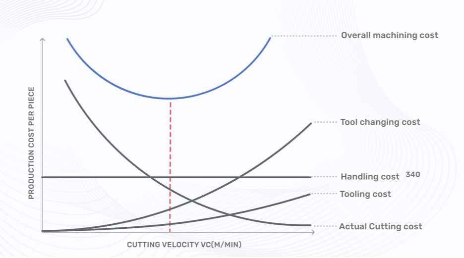
As you can see in the graph above, the feed rate (cutting velocity) function of cost is non-linear. As for smaller parts, since the feed rate is going to be lower, the costs are going to be higher. Then there is the surface finish problem. Cutting with tools creates a lot of forces. Consequently, creating some micro-vibrations. A smaller blank will be more prone to vibrations than a bigger blank, increasing the tolerances and decreasing the surface finish. There is also another unique problem associated with turning smaller components. It is all a consequence of the rudimentary physics formula v= rω (Linear velocity = Radius x Angular velocity). Increasing linear speed at the point of cutting with a low feed rate (of the tool) improves the surface finish. For a smaller component, increasing the linear speed at the point of cut will be difficult because of the smaller radius. One can achieve a mirror finish for a diametrically 100 mm component, but can never do quite the same for a diametrically 8 mm component. And there is also the problem with the tolerances. A 25-micron tolerance for a 200 mm component is not the same as the same tolerance for a 10 mm component. To sum it up, the Drone components are always machined with a low feed rate, with difficult jigs, and with high tolerances. But we can get around these issues with a few DFM tricks.
MATERIAL SELECTION AND HARDNESS FOR DRONE COMPONENTS
One, the material selection is crucial. It has always been, but as this problem gets accentuated when the size reduces, the material selection becomes even more paramount. The machinability is the ease at which a material can be cut by a cutting tool. There are a lot of parameters involved, but simply put, the harder the material, the lesser the machinability; it is measured in the machinability index. Choosing a softer material - than the requirement - and then increasing the hardness with post-machining processes should be the go-to strategy.
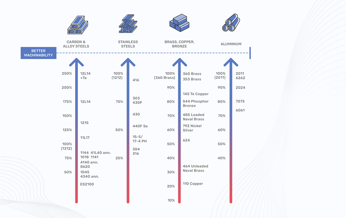
Harder materials also reduce the surface finish because of the rampant micro-vibrations. For example, if you are planning to design your Drone with an Aluminium structure, instead of going for a 7075 directly, you can use 2024-annealed during machining and then increase its hardness later with Anodization; Anodization can increase the hardness by 20-30%. The overall cost savings, in the material alone, will be 60% (including heat treatment costs, excluding the costs saved during machining).
TOLERANCES
Two, try giving open tolerances wherever you can. As mentioned earlier, tolerances must be tighter for a smaller component to have the same effect as a large component with nominal tolerances. But we must limit specifying tolerances only to where it is strictly necessary. For the component in the argument, the four holes and their drilling positions must be having tight tolerances, because of functional requirements. But in other regions, it can be ignored and let the supplier go with open tolerance. A mirror finish may aid the aesthetics. A drone, being a precision contraption, must have precise components.
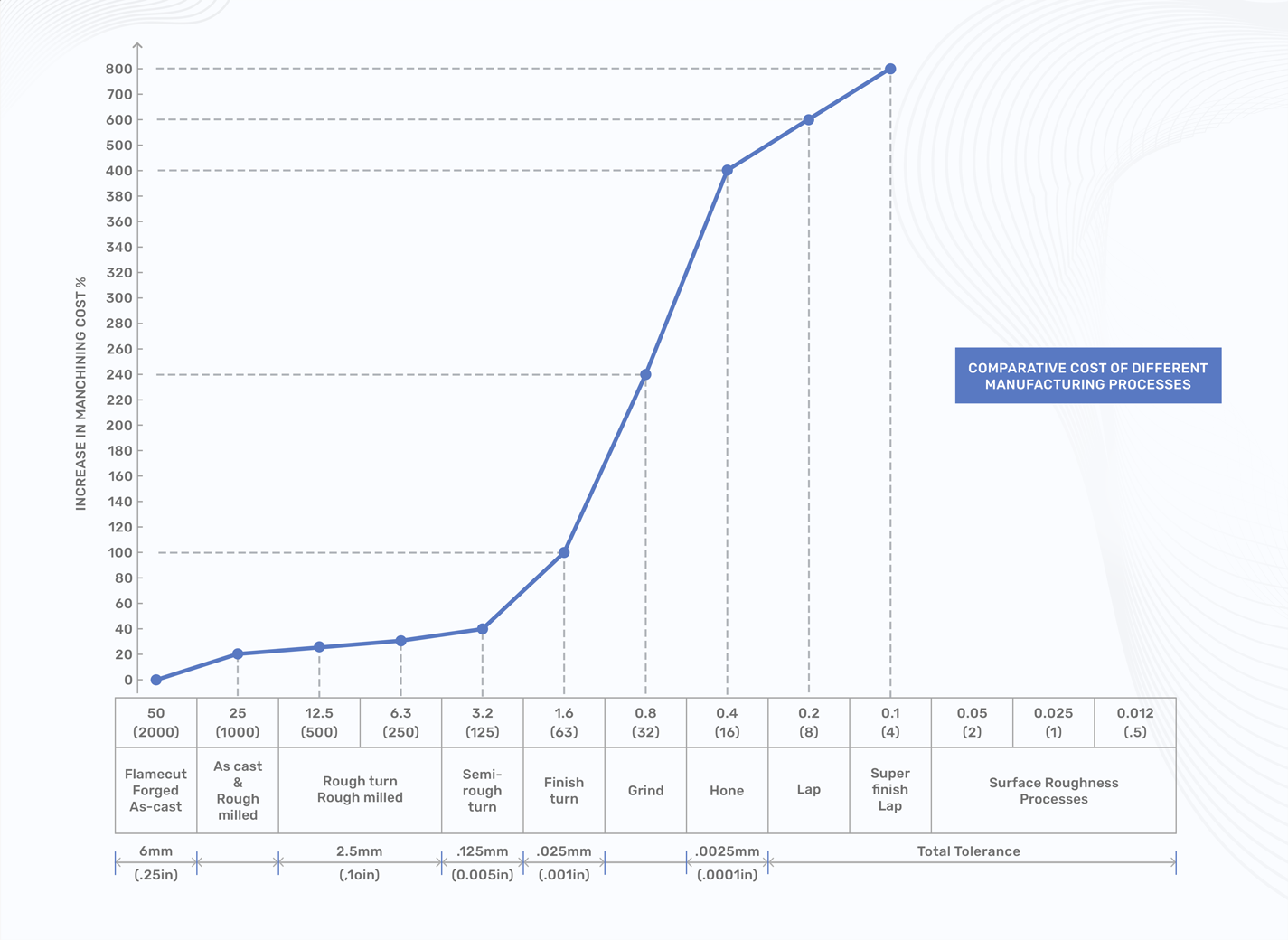
Like most cost-associated variables, tolerance’s function of cost is also non-linear causing the costs to grow disproportionally with increasingly tighter tolerances.
FEATURES
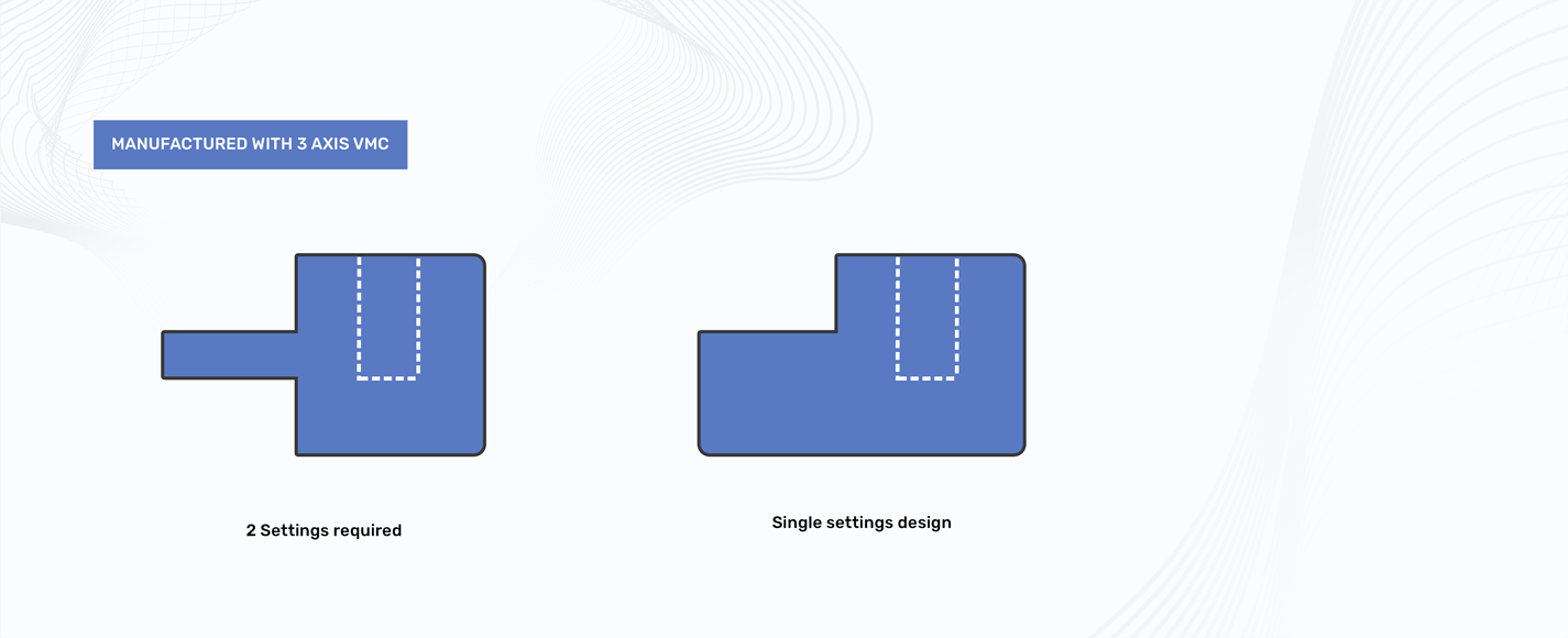
Three, limit features to the absolute minimum. Weight is paramount for any aerial vehicle, but so is cost. Avoiding features (holes, slots, some weird weight reduction cuts, etc) as much as it is humanly possible will do a great favor to your wallet. Even when you cannot avoid features, you should try your best to limit all the features to a single plane, which will reduce the setting time; and don’t forget “Time is money”. Our best advice is to try reducing weight in other areas (like material, optimization, reducing part count, integrating components, etc) if the cost is a major consideration for you. For example, take the simple component that is shown in the figure. The time required to manufacture the first one is almost fifty percent greater than the second one.
MULTI – BODY PARTS
Finally, if the component is intricate, avoid going monolith for production requirements. One can achieve a similar shape with welding, brazing, or even gluing, albeit with little wider tolerances. Carving monolith structures that have multiple features in a lot of different planes is almost equivalent to carving a statue out of a stone; it’s going to cost us a hell a lot of time. These four rudimentary rules can help you reduce machining costs and avoid DFM issues when developing your drone. And if you are looking to manufacture machining components for your drone, we can help you with it.
To Know more about our CNC Machining Solutions, Click here
To Know more about our manufacturing solutions for Drone components Click Here